Custom Module Design
![]()
![]() Custom modules can be designed by laying out loose pieces of track, sketching with pencil and paper, CAD, Visio, PowerPoint or even using track layout software intended for traditional layouts. The modules provided on this website were first sketched with pencil and paper and then modeled using Rhino 7.0. The process for creating these CAD models is described in detail below - in part as a reminder for me for when I imagine new designs. Basic steps are definition of the track centerline, offsets to approximate the rail groove, refinement of the rail groove intersections, offsets from the rail groove for the rail periphery and rail groove cutter path, and finally railroad ties if desired.
Custom modules can be designed by laying out loose pieces of track, sketching with pencil and paper, CAD, Visio, PowerPoint or even using track layout software intended for traditional layouts. The modules provided on this website were first sketched with pencil and paper and then modeled using Rhino 7.0. The process for creating these CAD models is described in detail below - in part as a reminder for me for when I imagine new designs. Basic steps are definition of the track centerline, offsets to approximate the rail groove, refinement of the rail groove intersections, offsets from the rail groove for the rail periphery and rail groove cutter path, and finally railroad ties if desired.
![]()
Track Centerlines
![]() The general path for each railway line is defined using lines, arcs or splines that enter and leave perpendicular to an end of the module. The minimum radius for the centerline of a curve is 4.1875" (consistent with a standard 3˝" curve). Spiral easements using ellipses or simply a large radius transitioning into a smaller one improve the overall flow and appearance of the finished railway. With CAD, conics and splines are relatively straightforward too. Combining small and large radii is also a strategy to align tracks without using a short straight section. Curved turnouts and shallow crossings are possible, but an angle less than about 30 degrees can be problematic. Join/Concatenate these centerline segments to create continuous curves where possible to streamline subsequent steps.
The general path for each railway line is defined using lines, arcs or splines that enter and leave perpendicular to an end of the module. The minimum radius for the centerline of a curve is 4.1875" (consistent with a standard 3˝" curve). Spiral easements using ellipses or simply a large radius transitioning into a smaller one improve the overall flow and appearance of the finished railway. With CAD, conics and splines are relatively straightforward too. Combining small and large radii is also a strategy to align tracks without using a short straight section. Curved turnouts and shallow crossings are possible, but an angle less than about 30 degrees can be problematic. Join/Concatenate these centerline segments to create continuous curves where possible to streamline subsequent steps.
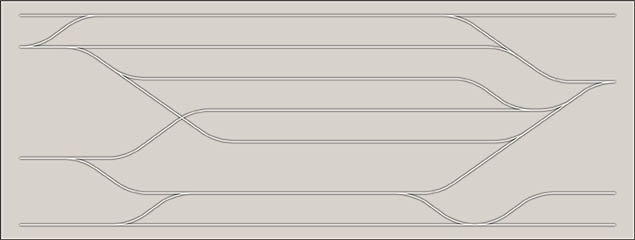
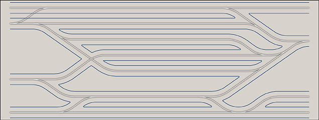
Module with track centerlines (white) defined and joined
![]()
Rail Slot Outlines
![]() The path for the cutter that actually mills the rail groove is a 0.500" offset from the centerline. Modeling representative rail slot geometry allows intersections at turnouts and crossings to be refined which is critical for shallow turnouts or crossings. This rail slot outline is also helpful when considering locations for segmenting the track and orienting the rail joiner - particularly if notched track ties are planned. Using the track centerlines (white), offset a curve at 0.38" and 0.62" in both directions. Select these offset curves and trim their intersections for a visual representation of the finished rail slot. Group these to easily hide/unhide as needed.
The path for the cutter that actually mills the rail groove is a 0.500" offset from the centerline. Modeling representative rail slot geometry allows intersections at turnouts and crossings to be refined which is critical for shallow turnouts or crossings. This rail slot outline is also helpful when considering locations for segmenting the track and orienting the rail joiner - particularly if notched track ties are planned. Using the track centerlines (white), offset a curve at 0.38" and 0.62" in both directions. Select these offset curves and trim their intersections for a visual representation of the finished rail slot. Group these to easily hide/unhide as needed.
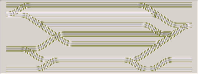
Module with rail slot outlines (khaki) defined, but not joined or segmented
![]()
Refining Rail Intersections
![]() Though time-consuming, rail intersections should be refined to improve tracking for smooth operation and a clean, finished appearance. This involves revising intersections so they taper by 5° to a corner with a 1/32" radius rather than ending as a sharp corner.
Though time-consuming, rail intersections should be refined to improve tracking for smooth operation and a clean, finished appearance. This involves revising intersections so they taper by 5° to a corner with a 1/32" radius rather than ending as a sharp corner.
Animation showing geometry and steps required
![]()
Track Outline
![]() Finished track is typically 1-5/8" in width - I've rounded to 1.624 because half is still a three-digit decimal... Using the outside rail intersections (a modified 0.62" distance from the centerline), offset a curve at 0.192" to establish the track periphery. Select these offset curves and trim the intersections to establish the actual outline of the track prior to segmentation. Presuming that a 1/8" Dia CNC cutter is used to cut the track periphery, fillet interior corners at 5/64" to ensure the cutter is 'driven' through the corner without a pause that can burnish or discolor the edge.
Finished track is typically 1-5/8" in width - I've rounded to 1.624 because half is still a three-digit decimal... Using the outside rail intersections (a modified 0.62" distance from the centerline), offset a curve at 0.192" to establish the track periphery. Select these offset curves and trim the intersections to establish the actual outline of the track prior to segmentation. Presuming that a 1/8" Dia CNC cutter is used to cut the track periphery, fillet interior corners at 5/64" to ensure the cutter is 'driven' through the corner without a pause that can burnish or discolor the edge.
Module with track outlines (blue) defined and filleted, but not segmented
![]()
Rail Tie Definition
![]() For a more detailed layout, notches representing a division/gap between ties can be modeled. These tie gaps can be cut or laser etched. Defining these centerlines takes some thought and eye-strain plus a few more minutes when cutting the track, but the result is well worth it. If undecided, at least lay out the point spacing - which will establish track segmentation in a logical way allowing you to add ties later without reworking your track outlines.
For a more detailed layout, notches representing a division/gap between ties can be modeled. These tie gaps can be cut or laser etched. Defining these centerlines takes some thought and eye-strain plus a few more minutes when cutting the track, but the result is well worth it. If undecided, at least lay out the point spacing - which will establish track segmentation in a logical way allowing you to add ties later without reworking your track outlines.
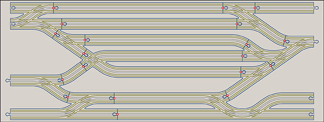
![]() Ties are typically spaced at ˝" intervals along the track centerline and perpendicular to it. Turnouts (switches) present a special challenge - one branch having diverging track centerlines (white). Starting at that point of divergence, create an intermediate curve that is equidistant from the rails (a 'tween' curve). Make a copy of your track centerlines (white) and trim them at the rail outline boundaries (khaki). This defines the segments in which ties are spaced. The intermediate curve (pink) splits the difference between the diverging lines and can be spliced into the track centerline segment.
Ties are typically spaced at ˝" intervals along the track centerline and perpendicular to it. Turnouts (switches) present a special challenge - one branch having diverging track centerlines (white). Starting at that point of divergence, create an intermediate curve that is equidistant from the rails (a 'tween' curve). Make a copy of your track centerlines (white) and trim them at the rail outline boundaries (khaki). This defines the segments in which ties are spaced. The intermediate curve (pink) splits the difference between the diverging lines and can be spliced into the track centerline segment.
Module with modified track centerline segments (pink and white) defined
![]()
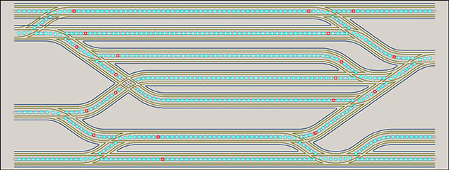
![]() Measure the length of each track centerline segment and divide into equal increments roughly ˝" apart. At switches where the lines diverge (pink), space at ˝" towards the open end. The result is shown below with points representing tie locations.
Measure the length of each track centerline segment and divide into equal increments roughly ˝" apart. At switches where the lines diverge (pink), space at ˝" towards the open end. The result is shown below with points representing tie locations.
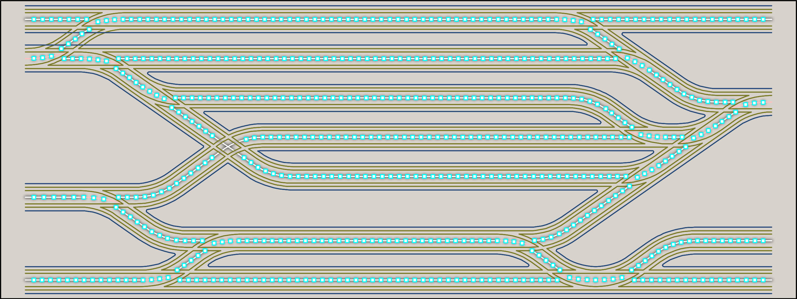
Module with tie notch locations (cyan points) defined
![]()
Track segmentation
![]() At this point, natural divisions for the track in the layout become apparent. Lumber widths are a limiting factor and grain direction matters too. Start with your most complicated track geometry (typically switches and crossings) and define break locations at a 'tie' location just beyond filleted corners (red points).
At this point, natural divisions for the track in the layout become apparent. Lumber widths are a limiting factor and grain direction matters too. Start with your most complicated track geometry (typically switches and crossings) and define break locations at a 'tie' location just beyond filleted corners (red points).
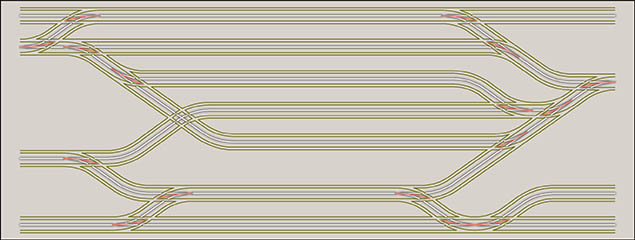
Proposed track segmentation locations (red points)
![]() Break the tie centerlines across these boundaries and then position joint pairs (male/female connectors) at these track boundaries. Split the track boundaries and joint with the joints to create discrete pieces of track.
Break the tie centerlines across these boundaries and then position joint pairs (male/female connectors) at these track boundaries. Split the track boundaries and joint with the joints to create discrete pieces of track.
Track segmentation
![]()
Rail Centerlines
![]() Rail centerlines (red) are a 0.12" offset from both of the the refined rail outlines.
Rail centerlines (red) are a 0.12" offset from both of the the refined rail outlines.
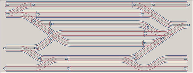
Rail Centerlines defined, but not segmented
![]()
Rail Centerline Segmentation
![]() The final step involves dividing the rail centerlines into individual track sections. Split the rail centerlines at track boundaries and then extend at each end by 5/64" to ensure the cutter will travel past the track boundary. Create lines that are normal to the centerline to define tie centerlines if needed - then trim to a rail outline offset to create an castellated cutter path for the tie grooves (olive).
The final step involves dividing the rail centerlines into individual track sections. Split the rail centerlines at track boundaries and then extend at each end by 5/64" to ensure the cutter will travel past the track boundary. Create lines that are normal to the centerline to define tie centerlines if needed - then trim to a rail outline offset to create an castellated cutter path for the tie grooves (olive).
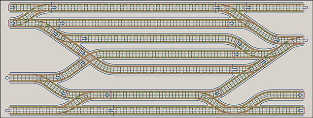
Completed track definition
![]()